Introduction
Digital circuit design can be simulated in a variety of simulators, ranging from expensive proprietary simulators like VCS or QuestaSim to free and open-source simulators like Verilator or Icarus Verilog.
The nature of these tools gives people the impression that all digital circuit simulators, no matter the format, are huge piles of code that utilize all sorts of fancy ideas and drive all way down to the rabbit hole of programming languages and digital circuit design.
While this is true for fully functional circuit simulators, the idea of basic digital circuit simulation is not that hard, and there are multiple paths to reach the final objective (depending on what objective we’re talking about). In this post, I’ll show how I am going to construct a proof-of-concept level digital circuit simulator that compiles circuit design into a Makefile and uses GNU Make to drive the cycle simulation. Here is the repo: rtl2makefile
Simulation Methodologies
There are many methodologies used in digital circuit simulation, including event-driven simulation, cycle-accurate/cycle-based simulation, and analog-level simulation. This post will mainly focus on cycle-accurate (more accurately, cycle-based) simulation.
Makefile based digital circuit simulation
GNU Make is a tool that controls the generation of executables and other non-source files of a program from the program’s source files.
It reads the modification date(one argument in inode struct) of a certain file and decides whether to run certain operations based on the dependency relationships defined in a file called “Makefile” This special characteristic is the key for us to mimic the behavior of digital circuits using Makefile.
For those who haven’t written any Makefiles, here is the basic structure of a Makefile:
a: b c
    $[command]
This means: once b or c changes, GNU Make will execute the specified command and update a. a can be a file or a virtual target. Once a has changed, all other targets that depend on a will also be updated, and GNU Make will execute their commands all way to the root of the dependency tree — this is exactly what digital circuit simulation is doing!
Combination logic simulation
Here is a simple AND gate written in verilog for reference:
wire a, b, c;
assign c = a & b;
The synthesizer would likely generate this circuit:
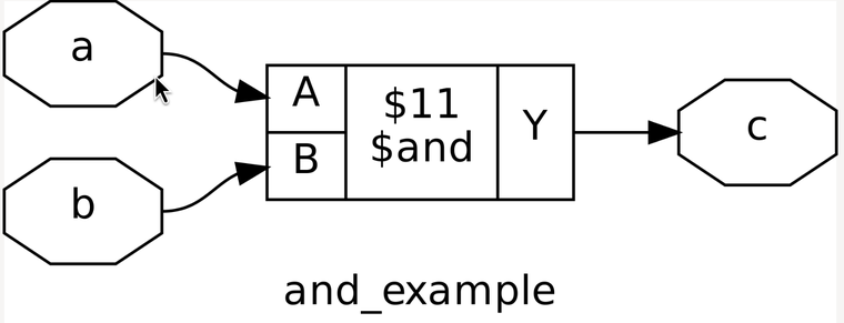
When a testbench drives any changes to either b or c, the value of a will also change. If we create a single file for each wire, we can mimic this operation through the execution of GNU Make.
Here is a small example of a compiled Makefile for a simple AND gate:
a: b c
        @b_val=$$(head -n 1 b); \
         c_val=$$(head -n 1 c); \
         result=$$((b_val + c_val)); \
         echo $$result > a
In the code above, once the value in file b or c changed, Make will execute a sequence of commands, which read value in file b and c, calculate the AND result, and write it back to file a.
Sequential logic simulation
It’s bit complicate for the case of sequential logic, since the value written to dff(for simplicity purpose we will ignore latch) can only be valid for read in next cycle.
In order to fix this problem, we split a single dff into 2 element: dff_d and dff_q.
They have the same meaning as what people frequently use in verilog/systemverilog: *_d for write and *_q for read(or *_d for *_current and *_q for *_next)
To imitate how a DFF behaves, we introduce a special tag file for each DFF. A tag file acts like a mandatory switch to enforce the update of a certain wire in the next cycle. For example, here is a non-resettable DFF in SystemVerilog:
always @(posedg clk)
    dff <= a;

assign b = dff;
Synthesizer would likely generate circuit like this:
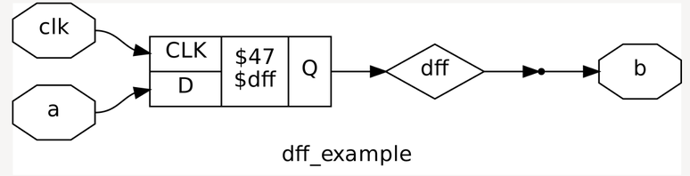
And the Makefile for this circuit looks like this:
dff_d: a
        @dff_d_val=$$(head -n 1 a); \
         echo $$dff_d_val > dff_d; \
         od -An -N4 -tu4 /dev/urandom | tr -d ' ' > dff_tag

dff_q: dff_tag
        @dff_q_val=$$(head -n 1 dff_d); \
         echo $$dff_q_val > dff_q
In the Makefile code above, When we change the value of a, dff_d will also change. But instead directly change the value of dff_q, it write a random number in dff_tag file, which dff_q depends on.
In this case, the next time we execute Make, dff_q will be update and change its value by reading the value inside dff_d.
Notice since this project only focus on dff, it assume all reg are dff and remove the need of clock signal.(To simulate clock signal, we need to take each make into even smaller granularity, which is over-complicate for this toy example)
In this case, we are able to simulate both combinational logics and sequential logics with dff. We can start doing compiler works.
HDL
Most widely used HDLs today are Verilog/SystemVerilog, but honestly speaking, they are terrible languages with lots of self-contradictory and vague descriptions in their specifications.
Also, from modern perspective of language design, Verilog/SystemVerilog adopt language design patterns that almost all programming languages nowadays try to avoid. Some people insist Verilog/SystemVerilog is NOT a programming language because they are actually design the hardware instead of randomly stacking instructions on the top of the memory, but some terrible designs also makes hardware design quirky and arcane(e.g. blurred boundary between synthesizable/unsynthesizable, inconsistent package manager/build system, random syntaxes and semantics from 80s, …)
Finally, the language spec is long and tedious to read.
Because of this, this post will not attempt to build a simulator for Verilog/SystemVerilog. Instead, I’m going to introduce an extremely small DSL as the source language for our simulator.
Lisp-liked DSL
The spec of our language is simple. It only supports one “module” for simulation. Here is a small example of a single adder:
(let
    (
        (wire a b)
        (wire c)
    )

    (circ
        (conn c
            (+ a b)
        )
    )
)
It doesn’t enforce bit-length rules yet, for simplicity, but it’s not hard to add those constraints in the future.
The first argument for our special let(or you can change it to circ-let) is the list of wire definitions. For now we only support wire and reg as the data type.
The second argument of let is the actual circuit design. It starts with circ, marking that we are going to describe a circuit.
The operators you can use in the circuit are +, -, *, /, &, |, ! plus conn.
The first few are straightforward. They generate different kinds of combinational circuits, takes 2 argument as input wire, and will return(or being evaluated) as a output wire.
conn takes two arguments a and b, and wires the result of b into a.
For example, (conn a b) results in a circuit that looks like:
b ---> a
It’s pretty intuitive for connection between wires and wires, but for connections between wires and regs complicated a little bit.
conn is able to make connection between wires and wires, wires and regs, but not regs and regs directly.
The reason is because of my internal laziness, and it’s also possible to define a temporal wire as the bridge between regs so it’s not a big problem ;)
That’s almost all of the language spec. It’s an extremely small language for describing digital circuits, and I will talk about how to design a compiler that compiles this language into Makefiles for simulation with GNU Make.
Compiler design
The reason I chose Lisp as the base language for my HDL is because it’s a great meta-programming language for language design. It has a simple syntax and a parser-friendly structure. Most importantly, the interpretation of Lisp follows the eval-apply meta loop, which makes it really easy to implement the compiler.
The compiler itself is written in Rust, mainly because of its amazing memory safety guarantees and strong package manager. (I tried using ANSI-C to write a Lisp interpreter, and I spent a lot of time debugging memory bugs and embedding a small GC.)
The file structure is also straightforward:
-
main.rs is where the REPL loop lives
-
frontend.rs handles reading and parsing
-
eval.rs implements the eval-apply loop
-
generator.rs is the “backend” of the compiler
-
types.rs contains a terribly designed type system — but it’s not the focus of this project, so I left it as is
Result
As a result, the compiler successfully generates the intended Makefile as well as the files representing each wire. Although I haven’t come up with a solid test scheme, the cycle-level wire dump shows it can imitate some simple combinational logic and a count-up counter.
In terms of resource consumption, this simulator surely uses memory, but it also consumes disk space. It does this by creating a lot of small files, eventually exhausting the inode count provided by the filesystem (assuming ext4). You can check the remaining inode count by running:
df -i
Conclusion
This project only serve for concept proof purpose, and I have no intend to extend/refine it. But it also shows that anything with the ability of polling and update can be used in circuit simulation.